Many things change the correct effective length of your pushrods, head surfacing, block surfacing, valve length, installed height of the valves etc.
We have tried to make this as easy as possible by creating a kit, which consists of:
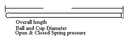
2-Checking adjustable pushrods
2-Solid lifters
We will charge you $50.00 for this kit, this will be credited to your purchase when we receive the kit back, so it’s virtually free.
We
need:
Valve spring seat pressure
Valve spring open pressure
Gross lift of cam at the valve
Duration at .050
Expected RPM
Solid, Hydraulic, Schubeck or Roller Cam
Head type as in stock cast, Indy, Edelbrock etc.
Valve brand, part number or if they we’re a Ready To Run head kit.
This information will help us determine the pushrod diameter and wall thickness required to carry the load.
Follow these instructions
Step 1:
Coat 1-intake and 1-exhaust valve tip with a black felt pen or Prussian Blue.
Step 2:
Watch the cam lobes and rotate engine until both valves are closed.
Step 3:
Set rocker arm adjuster to show about 2 threads out of the bottom on the rocker arm.
Step 4:
Install 2 solid lifters on the cam lobes that correspond with the two valves your working on. Please oil them so they don’t get damaged.
Step 5:
Install Push rods and adjust to approximate length
Step 6:
Assemble the 2 rocker arms on the shaft and install the shaft, use at least
3 hold-downs to be sure the shaft is down tight and square.
Step 7:
As you install the shaft assembly continue to adjust the pushrod until you have the shaft tight and your set at zero lash. Do Not Adjust the rocker arm; use the pushrod to adjust the lash. Tork the rocker shaft to 12-15 foot-pounds.
Step 8:
Rotate the engine clockwise until both valves have completed a cycle (2 revolutions of the crank)
Step 9:
Remove rocker shaft assembly and inspect the wear pattern on the valve tip, it should be right in the center.
Step 10:
So you have now determined the correct pushrod length. Lock down the pushrod and send both pushrods, one of your lifters and the two solid lifters supplied to:
Bend,
Oregon 97701
Tech Notes: Rocker arm and retainer/spring interference is possible if the heads have been modified. Once you have your pushrods correctly adjusted check and be sure you don’t have any interference, clearance of no less than .010. This interference is usually when the valve is in the closed position; as the valve opens the clearance issues disappear.
Depending on the rocker arm your using always check to be sure that the cup of the pushrod does not interfere with the body of the rocker arm. This may occur in the max lift position on the valve. If there’s contact you may have to go one more turn on the adjuster screw to eliminate the contact.
Also check to be sure the rocker arm body is not touching the top of the retainer in the closed position, again minimum of .010” between retainer and rocker arm at zero lash is recommended.
FBO Catalog Index